
As an ISO/IEC 17025 accredited (CNAS) independent laboratory, we provide specialized high-temperature molten salt testing services for concentrated solar power (CSP) plants, thermal energy storage systems, and industrial heat transfer applications in Algeria. With Algeria's ambitious renewable energy targets, including the development of CSP facilities in the Sahara region, reliable characterization of molten salt properties and material compatibility is critical. Our analyses cover the most common salt formulations (Solar Salt: 60% NaNO₃ / 40% KNO₃, Hitec: 53% KNO₃ / 40% NaNO₂ / 7% NaNO₃, Hitec XL, and chloride or carbonate salts for next‑generation high‑temperature storage), evaluating thermal stability, corrosion rates, thermophysical properties, and long‑term performance under realistic operating conditions.
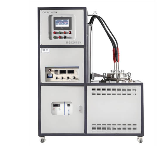
Types of Molten Salt Samples and Components We Test
- Solar Salt (60 wt% sodium nitrate / 40 wt% potassium nitrate) – the most widely used heat transfer and storage medium in commercial CSP plants
- Hitec salt (53% KNO₃ / 40% NaNO₂ / 7% NaNO₃) – lower melting point (142°C) suitable for medium‑temperature applications
- Hitec XL (calcium nitrate / potassium nitrate / sodium nitrate) – reduced freezing risk
- Chloride salts (NaCl, KCl, MgCl₂, CaCl₂ mixtures) – for next‑generation high‑temperature CSP (>700°C)
- Carbonate salts (Li₂CO₃, Na₂CO₃, K₂CO₃ mixtures) – for supercritical CO₂ Brayton cycle integration
- Nitrate salt samples taken from operating CSP plants (used salt analysis, degradation assessment)
- Metallic coupons and components (stainless steel 304, 316L, 347; nickel alloys Inconel 625, 718, Hastelloy C‑276, Incoloy 800H; carbon steel for tankage)
- Protective coatings and cladding materials applied to molten salt containment vessels and piping
- Thermal insulation materials in contact with molten salt vapors or spillage
- Gasket and sealing materials for pumps, valves, and flanged connections
Molten Salt Thermophysical Property Characterization
- Melting point and freezing point determination (differential scanning calorimetry – DSC) – Accurate measurement of solid‑liquid phase transition temperatures. For Solar Salt, the melting point is typically 220–225°C. Deviations indicate impurity accumulation or compositional change. We also measure the heat of fusion (enthalpy) which relates to the sensible and latent heat storage capacity.
- Decomposition temperature (thermogravimetric analysis – TGA) – Under nitrogen or air atmosphere, the sample is heated from ambient temperature to 800°C. The onset of mass loss indicates the maximum safe operating temperature. For nitrate salts, decomposition begins around 550–600°C, releasing oxygen and forming nitrites, oxides, and other products. A stable salt should show less than 1% mass loss after 2 hours at the intended maximum operating temperature (typically 560°C for Solar Salt).
- Specific heat capacity (Cp) measurement by modulated DSC or three‑sample method – Determined in both solid and liquid phases. Cp values are required for thermal energy storage calculations (Q = m × Cp × ΔT). Typical Cp of Solar Salt in the liquid phase (300–500°C) ranges from 1.45 to 1.60 J/g·K.
- Thermal conductivity and thermal diffusivity (laser flash analysis – LFA) – Measured on solidified salt samples or using specialized liquid cells. Thermal conductivity affects heat transfer rates to and from the storage medium. For Solar Salt at 400°C, thermal conductivity is approximately 0.5–0.6 W/m·K.
- Viscosity as a function of temperature (rotational viscometry with high‑temperature furnace) – Viscosity influences pumping power and flow distribution in solar receiver tubes and storage tanks. For Solar Salt at 400°C, viscosity is typically 1.8–2.5 cP. We measure viscosity from just above the melting point up to 600°C.
- Density of molten salt (Archimedean method or pycnometry at elevated temperature) – Density data are essential for tank sizing and natural circulation calculations. The density of Solar Salt decreases linearly with temperature: about 1.92 g/cm³ at 300°C, 1.87 g/cm³ at 500°C.
- Vapor pressure measurement (effusion method or thermogravimetric‑mass spectrometry coupling) – Low vapor pressure is desirable to minimize salt loss and fouling of heat exchange surfaces. Nitrate salts have very low vapor pressure below 550°C.
Corrosion Testing – Material Compatibility with Molten Salts
Corrosion is one of the most critical concerns for CSP plant operators. The molten salt, especially when contaminated with chlorides, moisture, or decomposition products, can attack metal surfaces, leading to thinning, pitting, intergranular attack, and ultimately failure of pipes, tanks, and heat exchangers. Our corrosion testing services include:
- Static immersion corrosion test (coupon method) – Pre‑weighed and measured metal coupons (typically 25 mm × 25 mm × 2–5 mm) are fully immersed in molten salt contained in alumina or stainless steel crucibles under controlled atmosphere (air, argon, or synthetic air). Tests are conducted at intended service temperatures (e.g., 390°C, 450°C, 500°C, 560°C, 700°C for chloride salts) for durations ranging from 100 to 2000 hours. After exposure, coupons are removed, carefully cleaned to remove adherent salt, and reweighed. Mass loss is converted to corrosion rate in mm/year or mg/cm²·hour. Surface morphology is examined by scanning electron microscopy, and cross‑sections are analyzed for depth of attack (intergranular, pitting, uniform).
- Dynamic corrosion test (rotating coupon or flowing salt loop) – More representative of real plant conditions where the molten salt flows across metal surfaces. A rotating impeller agitates the salt past fixed coupons (linear velocity controlled) or a recirculating loop with a pump and heated sections circulates molten salt through test sections containing coupon specimens. Flow accelerates corrosion by removing boundary layers and protective oxide scales. Dynamic corrosion rates are typically 2 to 5 times higher than static rates.
- Thermal cycling corrosion test – Simulates daily start‑up and shut‑down of CSP plants. Coupons are exposed to alternate cycles: heating above the salt melting point (e.g., 300°C to 560°C), holding for several hours, then cooling below the freezing point (e.g., down to 200°C). After 100 to 500 cycles, coupons are examined for cracking, spalling of oxide scales, and accelerated corrosion due to thermal expansion mismatch.
- Galvanic corrosion test (bimetallic couple) – When two dissimilar metals are connected in the molten salt circuit (e.g., stainless steel piping with nickel alloy valves), galvanic corrosion can occur. We measure the galvanic current and corrosion potential between coupled metal pairs immersed in molten salt.
- Crevice corrosion test (simulated flange or gasket interface) – Specially designed fixtures create a crevice between a metal coupon and a ceramic or PTFE washer. After exposure, the crevice region is examined for localized attack, which can initiate pitting and stress corrosion cracking.
- Stress corrosion cracking (SCC) testing (constant load or slow strain rate) – For components under mechanical stress (e.g., expansion bellows, threaded connections, welded joints). A tensile specimen is immersed in molten salt while being loaded to a percentage of its yield strength or subjected to a slow extension rate (typically 10⁻⁶ to 10⁻⁷ s⁻¹). Time to failure and fracture surface analysis identify susceptibility to SCC.
Molten Salt Chemical Purity and Degradation Analysis
- Nitrite content determination (by titration or ion chromatography) – In nitrate salts, thermal decomposition and reaction with oxygen produce nitrite ions (NO₂⁻). High nitrite content lowers the melting point but also increases corrosivity. Fresh Solar Salt typically contains less than 0.5 wt% nitrite. After extended operation, nitrite levels may rise to 1–3%. We quantify nitrite using permanganate titration or ion chromatography.
- Chloride ion concentration (ion chromatography or mercurimetric titration) – Chlorides are highly aggressive and accelerate pitting and intergranular corrosion. Chlorides can enter the salt from impurities in raw materials, from hydrochloric acid used in cleaning, or from decomposition of organic contaminants. Acceptable chloride limits for CSP nitrate salts are generally below 0.05% (500 ppm).
- Sulfate content (gravimetric or ion chromatography) – Sulfates can form hard deposits on heat transfer surfaces, reducing efficiency. They originate from raw material impurities or from oxidation of sulfur‑containing compounds.
- Water and moisture content (Karl Fischer titration or thermogravimetry) – Moisture accelerates corrosion at start‑up and can lead to foaming and pressure buildup. Fresh salt should contain less than 0.5% water; preferably below 0.1% for critical applications.
- Calcium, magnesium, and other cationic impurities (ICP‑OES or ICP‑MS) – High levels of Ca²⁺, Mg²⁺, Fe³⁺, or other multivalent cations can form insoluble oxide or carbonate deposits and may catalyze salt decomposition.
- Decomposition product analysis (alkalinity measurement) – As nitrate salts decompose, they become more basic. We measure the free oxide ion concentration (O²⁻) by titration with standard acid or by measuring the basicity index.
- Dissolved metals (from corrosion) in the salt (ICP‑MS after salt dissolution) – After exposure of metal coupons, the salt is analyzed for dissolved iron, chromium, nickel, and other alloying elements. The concentration of dissolved metals indicates the severity of corrosion and can help identify the type of attack (e.g., selective leaching of chromium).
Container and Structural Material Characterization
- Oxide scale analysis on exposed coupons (SEM‑EDS and X‑ray diffraction – XRD) – After corrosion testing, the protective oxide layer that forms on the metal surface is examined. For stainless steels in nitrate salts, a mixed oxide layer of Fe₂O₃, Cr₂O₃, and NiFe₂O₄ is typically observed. The thickness (measured from cross‑sections), composition, and spallation tendency of the scale are recorded. A dense, adherent, chromium‑rich scale indicates good corrosion resistance.
- Intergranular attack depth (metallographic examination after etching) – Cross‑sectioned coupons are mounted in resin, polished, and chemically etched to reveal grain boundaries. The maximum and average depth of intergranular penetration is measured under an optical microscope. Acceptable limits depend on component design life (typically <50 µm for a 25‑year tank life).
- Carburization or decarburization assessment (microhardness traverse and EDS carbon mapping) – In certain salt environments (especially carbonates and chlorides at high temperature), carbon can diffuse into or out of the metal, altering its mechanical properties. We measure the hardness profile from the surface inward and use electron probe microanalysis to map carbon concentration.
- Hydrogen embrittlement risk assessment (hydrogen content measurement by inert gas fusion) – Hydrogen can be produced by reaction of moisture with metals or from decomposition of organic contaminants. Hydrogen uptake can lead to embrittlement of high‑strength alloys. We measure hydrogen content in as‑exposed coupons and compare to unexposed controls.
Special Tests for CSP Plant Operations
- Salt freeze‑thaw cycling (simulated cold start) – CSP plants in desert regions may experience salt freezing in pipes and tanks during overnight or seasonal shutdowns. We perform repeated freeze‑thaw cycles (e.g., 50 cycles from 560°C down to 150°C and back up) and examine the salt for cracking, segregation, and changes in melting behavior. Containment materials are inspected for cracking caused by volume expansion during freezing (nitrate salts expand by approximately 4% upon solidification).
- Fouling and deposit formation test (on simulated heat transfer surfaces) – Salt mist or aerosol is generated and deposited onto heated metal tubes. The deposit adhesion strength, composition, and effect on heat transfer are evaluated. This test helps predict maintenance intervals for receiver tubes.
- Thermal stability after long‑term aging (accelerated life testing) – Salt samples are held at maximum operating temperature (e.g., 560°C for Solar Salt) for extended periods (1000, 2000, 5000 hours) in sealed crucibles. Periodically, aliquots are removed to measure nitrite content, melting point, decomposition onset, and corrosivity. An acceptable salt should maintain its properties for the design life of the plant (typically 25–30 years) without excessive degradation.
- Compatibility with containment vessel insulation – Insulating materials (ceramic fiber, mineral wool, calcium silicate) are exposed to molten salt vapors or direct contact. We measure salt absorption, capillary rise, mechanical degradation, and any exothermic reactions that could lead to fire.
Reporting and Deliverables
Each high‑temperature molten salt project report includes the following information:
- Complete identification of the salt sample (composition, supplier, batch number) and of any metal coupons (alloy type, heat treatment condition, surface finish, welding details if applicable)
- Test conditions: temperature profile, atmosphere (air, argon, synthetic air), duration, flow conditions (static or dynamic, velocity), number of thermal cycles
- Results of thermophysical property measurements (DSC thermograms with melting point and heat of fusion, TGA curves showing decomposition onset, viscosity vs. temperature data, thermal conductivity values, density data)
- Chemical purity results: nitrite content, chloride content, sulfate content, moisture content, cationic impurities (Ca, Mg, Fe, Al, etc.)
- Corrosion test results: mass change of coupons (mg/cm²), calculated corrosion rate (mm/year), surface and cross‑sectional SEM images, EDS spectra of surface scales, depth of intergranular attack (µm), photographs of any pitting or localized corrosion
- Assessment of salt degradation: changes in melting point, nitrite accumulation, alkalinity, and dissolved metal content after long‑term aging
- Comparison with client‑supplied acceptance criteria (if provided)
- Raw data, calibration certificates of instruments, photographs of coupons before and after testing, and metallographic images are included as appendices upon request
No general statements of compliance with any external code or standard are made unless the client has provided specific pass/fail criteria in writing. All raw data and samples are retained in our quality management system for a minimum of 10 years.
Why Choose ZKGX?
- State-of-the-art analytical equipment
- Highly qualified scientific team
- Fast turnaround time
- Competitive pricing