Understanding Shear Strength Test – Comprehensive Guide to Material Shear Properties for Engineering Design and Quality Control
As an ISO/IEC 17025 accredited (CNAS) independent laboratory, we provide expert shear strength testing services for manufacturers, engineers, and quality control professionals in Algeria. Shear strength is the maximum resistance of a material to shearing forces — forces that cause one layer of material to slide over an adjacent layer. Unlike tensile or compressive strength, shear strength is critical for components subjected to torsion, bending with transverse loads, bolted and riveted joints, adhesive bonds, welds, and punch operations. Our laboratory performs shear tests on metals, plastics, composites, adhesives, fasteners, and structural assemblies using specialized fixtures and universal testing machines. Results guide design decisions, verify material specifications, and ensure safety in aerospace, automotive, construction, and general manufacturing applications.
Types of Samples We Test for Shear Strength
- Metallic sheets, plates, and bars (steel, aluminum, copper, titanium, brass, bronze)
- Plastic and polymer materials (thermoplastics, thermosets, reinforced plastics, fiber composites)
- Fasteners (bolts, screws, rivets, pins, studs, nuts with threads)
- Adhesive bonds (lap shear specimens for structural adhesives, epoxy, polyurethane, acrylic)
- Welded joints (butt welds, fillet welds, spot welds, friction welds)
- li>Composite laminates (carbon fiber, glass fiber, aramid fiber reinforced polymers)
- Wood and engineered wood products (plywood, OSB, glulam, finger joints)
- Punching and blanking scrap (for evaluating stamping operations)
- Geotechnical materials (soils, weak rocks, asphalt mixtures) – available on request
- Electrical and electronic components (solder joints, lead attachments, wire bonds)
Theoretical Background – What is Shear Strength?
Shear strength (τ, tau) is defined as the maximum shear stress a material can withstand before failure occurs along a plane parallel to the direction of the applied force. The unit is force per area (MPa, psi, or kg/mm²). For isotropic materials, shear strength is approximately 0.5 to 0.8 times the tensile strength, depending on the material's ductility. For brittle materials (cast iron, ceramics), shear strength can be lower (0.2–0.4 times tensile strength). For anisotropic materials (composites, 3D printed parts, wood), shear strength depends strongly on the orientation of the applied shear relative to material structure.
Shear failure occurs in two primary modes: direct shear (punching or cutting through) and torsional shear (twisting). In direct shear tests, the force is applied parallel to the plane of interest. In torsional shear tests, a torque creates shear stress distributed around a circular cross-section. Our laboratory focuses on direct shear methods, which are more common for flat materials and joints.
Direct Shear Test Methods
The most common shear test configurations used in our laboratory are described below.
- Single‑lap shear test (for adhesives and bonded joints) – Two overlapping adherends (metal or plastic strips) are bonded together with the adhesive of interest. The assembly is pulled in tension, creating a shear stress along the bond line. The test is performed on a universal testing machine with hydraulic or pneumatic grips. The load is applied at a constant crosshead speed (e.g., 1–10 mm/min depending on the adhesive). The maximum load (F_max) is recorded, and shear strength is calculated as τ = F_max / (overlap length × specimen width). We also record the failure mode: cohesive failure (within the adhesive layer), adhesive failure (at the interface), or mixed failure. For ductile adhesives, the shear stress‑displacement curve may show yielding before fracture.
- Double‑lap shear test (for higher accuracy) – Similar to single‑lap but with the specimen sandwiched between two identical adherends on each side. This configuration reduces the peel stress component and provides a purer shear stress state, especially for brittle adhesives and composites. The calculation uses the total bonded area (both sides).
- Punch shear test (for sheets, films, and thin materials) – A punch tool (cylindrical or rectangular) is forced through a clamped sheet specimen, shearing the material along the periphery of the punch. The maximum punch force is recorded, and shear strength is calculated as τ = F_max / (shear area = punch perimeter × sheet thickness). This method is fast and requires minimal sample preparation. It is suitable for quality control of metal sheets and plastic films. The shear edge condition (sharp vs. dull) affects results; we use calibrated punches.
- Double‑shear test (for fasteners and pins) – A fastener (bolt, rivet, or pin) is placed across two support blocks, and a loading fork applies force to the middle of the fastener, creating two shear planes. The ultimate shear load is recorded, and the shear strength is calculated as τ = F_max / (2 × cross‑sectional area of the fastener). This method conforms to common fastener test standards and provides a direct measure of the fastener’s shear capability independent of tensile strength.
- Single‑shear test (for rivets and small pins) – The fastener is placed in a fixture that shears it across one plane. This is simpler but less representative of real joints where double shear is common. The calculated shear strength uses the single cross‑section area.
- Iosipescu (V‑notch) shear test (for composites and plastics) – A rectangular specimen with two V‑notches (one on each edge) is loaded in a special fixture that creates a pure shear stress state in the region between the notches. This method is ideal for anisotropic materials where shear properties need to be measured without interference from normal stresses. We use strain gauges or digital image correlation to measure shear strain, and the shear modulus (G) and shear strength are determined from the stress‑strain curve.
- Rail shear test (for composite laminates) – A flat rectangular specimen is clamped between two rails that apply opposing forces, inducing a shear stress in the specimen. This method is effective for measuring in‑plane shear properties of continuous fiber composites.
- Torsion shear test (for round bars and tubes) – The specimen is twisted about its axis on a torsion testing machine. Torque (T) and angle of twist (θ) are recorded. The maximum shear stress at the outer fiber is calculated using the torsion formula: τ_max = T × r / J, where r is the radius and J is the polar moment of inertia. For plastic materials, this method reveals the shear yield strength and the shear modulus (G = τ/γ).
Sample Preparation for Shear Testing
- Dimensional accuracy – Specimens must be machined or prepared to precise dimensions (±0.1 mm for width and thickness, ±0.01 mm for critical dimensions). For composites, water jet or diamond saw cutting is used to avoid delamination.
- Surface condition – For adhesive lap shear tests, the bonding surfaces are abraded (sandpaper or grit blasting) and cleaned with solvent to remove oil and dust. For metal shear tests, surfaces should be free of scale, rust, and deep scratches.
- Grip alignment – Misalignment introduces bending moments that can reduce measured shear strength. We use self‑aligning grips and check fixture parallelism before each test series.
- Conditioning (for plastics and adhesives) – Specimens are conditioned at 23°C ± 2°C and 50% ± 10% RH for at least 24 hours before testing, unless otherwise specified. For environmental simulations, we condition at elevated temperature, low temperature, or after humidity exposure.
- Number of replicates – We typically test 5 specimens for each condition to obtain a statistically valid average and standard deviation. For high‑precision applications (aerospace, medical devices), up to 10 replicates may be required.
Factors Affecting Shear Strength Measurements
Understanding these factors helps interpret results correctly and compare across different studies or production batches.
- Test speed (loading rate) – Many materials (especially polymers and adhesives) are strain‑rate sensitive. Higher test speeds generally increase measured shear strength but reduce elongation to failure. Our reports always include the crosshead speed or loading rate used.
- Temperature – Shear strength decreases with increasing temperature for most materials. For plastics, a 10°C rise can reduce shear strength by 5–15%. We control temperature via environmental chambers.
- Moisture content – Nylon and other hygroscopic polymers absorb moisture, which plasticizes the material and reduces shear strength. Specimens are dried or conditioned as specified.
- Test fixture geometry – For lap shear tests, the overlap length, adherend thickness, and presence of spew fillets influence the stress distribution and measured strength. Short overlaps produce higher apparent shear strength due to constraint effects, but values may not represent large joints. We follow standardized geometries for comparability.
- Anisotropy (for composites and 3D printed parts) – Shear strength measured parallel to layers can be 2–5 times higher than shear strength measured perpendicular to layers. We always note the orientation relative to the print or fiber direction.
- Specimen defects – Voids, porosity, inclusions, and surface scratches act as stress concentrators and reduce measured shear strength. We visually inspect each specimen before testing and note any anomalies.
Interpreting Shear Strength Results – Practical Guidelines
For design engineers, knowing the shear strength value alone is insufficient; they also need to understand the failure mode and stress distribution. The following guidance is based on our extensive testing experience.
- Ductile metals (mild steel, aluminum, copper) – Shear failure occurs after significant plastic deformation. The shear strength from a direct shear test is close to the ultimate tensile strength multiplied by 0.6 (von Mises yield criterion). For rivet design, use the manufacturer’s certified double‑shear strength.
- Brittle metals (cast iron, high‑carbon steel in hardened condition) – Shear failure is sudden with little deformation. Shear strength is approximately 0.3–0.5 times tensile strength. Design with higher safety factors (≥ 4).
- Adhesives – Lap shear strength values are highly dependent on the adhesive thickness, overlap area, and surface preparation. Do not compare values obtained from different adherend materials or different overlap lengths. Cohesive failure (crack within the adhesive layer) is preferred over adhesive failure (separation at the interface).
- Composites – In‑plane shear strength is usually lower than tensile strength. The Iosipescu or rail shear methods provide reliable values. For bolted joints in composites, the bearing strength (not pure shear) often governs design.
- Wood – Shear strength parallel to grain is much lower (by factor of 4–8) than shear strength perpendicular to grain. For structural timber, the failure mode is typically along the grain.
Common Standards and Reference Values (For Guidance Only)
While we do not certify to specific standard numbers without client specification, the following typical shear strength ranges are provided as reference for common materials.
- Low‑carbon steel (A36): shear strength ≈ 200–250 MPa (double‑shear)
- Stainless steel 304 (annealed): shear strength ≈ 300–350 MPa
- li>Aluminum 6061‑T6: shear strength ≈ 200–220 MPa
- Copper (hard drawn): shear strength ≈ 150–180 MPa
- Cast iron (gray): shear strength ≈ 130–180 MPa
- Polycarbonate (injection molded): shear strength ≈ 55–65 MPa (punch shear)
- Nylon 6/6 (dry): shear strength ≈ 45–55 MPa
- ABS: shear strength ≈ 30–40 MPa
- Epoxy adhesive (structural, on steel): lap shear strength ≈ 15–30 MPa (depending on cure and surface)
- Plywood (shear through thickness): ≈ 4–8 MPa
Reporting and Deliverables
Each shear strength test report includes the following information:
- Sample identification (material type, geometry, orientation, surface preparation, conditioning history)
- Test method (single‑lap, double‑lap, punch, double‑shear, Iosipescu, etc.) with clear description of fixture and setup
- Test conditions: temperature, humidity, crosshead speed (mm/min), preload (if any), and number of replicates
- Individual results: maximum load (N), shear area (mm²), calculated shear strength (MPa) for each specimen
- Statistics: average shear strength, standard deviation, coefficient of variation (%), and range
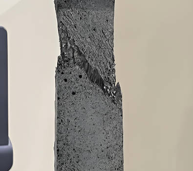
- Failure mode description and photographs (cohesive, adhesive, tearing, brittle fracture, etc.)
- Load‑displacement curve (upon request) showing the test progression
- Comparison with client‑supplied acceptance criteria (if provided) – pass/fail statement
- Raw data and testing machine calibration records are archived for 10 years
No statement of compliance with any external standard or regulation is made unless the client has provided specific acceptance criteria in writing.
Why Choose ZKGX?
- State-of-the-art analytical equipment
- Highly qualified scientific team
- Fast turnaround time
- Competitive pricing