Yang's Modulus Measurement – Accurate Determination of Material Stiffness for Engineering Design and Quality Control
As an ISO/IEC 17025 accredited (CNAS) independent laboratory, we provide precise Young's modulus measurement services for manufacturers, research institutions, and engineering firms in Algeria. Young's modulus (also known as the elastic modulus or tensile modulus) is a fundamental mechanical property that describes a material's stiffness — its resistance to elastic deformation under load. It is defined as the ratio of tensile stress to tensile strain within the elastic (linear) region of the stress‑strain curve. Accurate modulus values are essential for finite element analysis, structural design, material selection, and quality control of metals, plastics, composites, ceramics, elastomers, and 3D printed components. Our laboratory employs high‑precision universal testing machines equipped with advanced extensometers (contact and non‑contact) to measure strain with high resolution, ensuring reliable modulus values for both rigid and flexible materials.
Types of Samples We Test for Young's Modulus
- Metallic materials (steel, aluminum, copper, titanium, brass, bronze, cast iron, alloy steels)
- Plastics and polymers (thermoplastics: ABS, PC, PA, POM, PP, PE, PET, PVC; thermosets: epoxy, phenolic, polyurethane)
- Fiber‑reinforced composites (carbon fiber, glass fiber, aramid fiber, natural fiber composites, laminates, sandwich panels)
- Elastomers and rubbers (natural rubber, SBR, NBR, EPDM, silicone, polyurethane elastomers) – for these, we measure the initial slope (small‑strain modulus)
- Ceramics and glasses (alumina, zirconia, silicon carbide, silicate glasses, ceramic matrix composites)
- Wood and engineered wood products (solid wood, plywood, OSB, MDF, glulam, LVL) – measured parallel and perpendicular to grain
- 3D printed parts (FDM, SLA, SLS, SLM) – with modulus measured in different build orientations (XY, XZ, ZX)
- Thin films and sheets (polymer films, metal foils, paper, membrane materials)
- Biomaterials and medical device components (bone mimics, dental materials, catheter tubing, implant prototypes)
- Construction materials (concrete, mortar, fiber‑reinforced cement, asphalt mixtures – measured in compression)
Theoretical Background – What is Young's Modulus?
Young's modulus (E) is defined by Hooke's law within the elastic region: σ = E × ε, where σ is the tensile stress (force per unit cross‑sectional area, MPa) and ε is the tensile strain (change in length divided by original length, dimensionless). Therefore E = σ / ε, expressed in gigapascals (GPa) or megapascals (MPa). A high modulus indicates a stiff material (e.g., steel ~200 GPa, aluminum ~70 GPa, glass ~70 GPa), while a low modulus indicates a flexible material (e.g., polyethylene ~0.8 GPa, rubber ~0.01 GPa). The modulus is independent of sample geometry when measured correctly, making it an intrinsic material property. However, it can be influenced by temperature, strain rate, moisture content (for hygroscopic polymers), and anisotropy (direction‑dependent properties in composites, wood, and 3D printed parts).
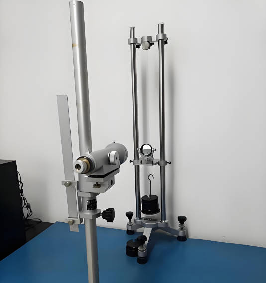
Measurement Principle and Test Setup
Young's modulus is determined from the initial linear portion of the stress‑strain curve obtained during a tensile test. The critical requirements for accurate modulus measurement are precise strain measurement and proper alignment.
- Universal testing machine (UTM) – We use electromechanical UTMs with load cells ranging from 100 N to 250 kN, depending on specimen cross‑section and material stiffness. The machine must have sufficient stiffness to not contribute significantly to the measured compliance.
- Strain measurement – contact extensometer – For rigid materials (metals, hard plastics, composites), we attach a clip‑on extensometer directly to the specimen. The gauge length (typically 25 mm, 50 mm, or 80 mm) is selected based on specimen geometry. The extensometer measures displacement with a resolution of 0.001 mm or better. For low modulus materials, very light‑weight extensometers are used to avoid specimen deformation under the weight of the device.
- Strain measurement – non‑contact video extensometer (optical) – For thin films, elastomers, temperature‑sensitive materials, or small specimens where contact would damage the surface, we use a high‑resolution camera with tracking marks applied to the specimen. The system tracks the displacement of two reference marks (or a pattern) and calculates strain with accuracy comparable to contact extensometers. This method is also ideal for high‑temperature testing (up to 300°C inside an environmental chamber) and for materials that undergo large elongation before failure.
- Strain measurement – strain gauges (for precision modulus on rigid materials) – For critical applications (aerospace, medical implant certification), we bond electrical resistance strain gauges (single or biaxial) to the specimen. The gauge factor and bridge circuit provide strain resolution down to 1 microstrain (10⁻⁶). This method eliminates any machine compliance error and is considered the reference method for modulus determination.
- Test speed (strain rate control) – Strain rate significantly affects modulus for polymers and elastomers. We control the test speed using strain rate control (e.g., 0.00025 s⁻¹ to 0.01 s⁻¹ for metals, 0.001 s⁻¹ to 0.1 s⁻¹ for plastics) or crosshead speed control (e.g., 1 mm/min for rigid plastics, 10 mm/min for films, 50 mm/min for elastomers). The test speed is always reported.
- Preloading and specimen alignment – Before starting the test, we apply a small preload (typically 0.5% to 2% of expected yield load) to take up slack and ensure the specimen is straight and centered. Misalignment introduces bending, which reduces the measured modulus. We use self‑aligning grips and verify alignment with a dummy strain‑gauged specimen annually.
Calculation Methods for Young's Modulus
Several methods are used to calculate the modulus from the stress‑strain data, depending on the material's linearity and the presence of an initial toe region (non‑linearity due to specimen seating).
- Secant modulus method (for materials with an initial curved region) – Some materials (e.g., some plastics, rubbers, composites, paper) show a non‑linear initial response due to bedding‑in of fibers, alignment of chains, or taking up of slack. The secant modulus is calculated between two defined strain points (e.g., 0.05% and 0.25% strain, or 0.1% and 0.5% strain). The specific strain range is reported. This method is common for plastics and composites.
- Linear regression (least squares) through the linear region (for most metals and rigid plastics) – A best‑fit straight line is applied to the stress‑strain data over the range where the material exhibits linear elastic behavior. For metals, this range is typically from 10% to 50% of the yield strain (or up to the proportional limit). For plastics, the linear region may be more limited. We use an automated algorithm that selects the longest consecutive range with R² > 0.999. The slope of the regression line is the Young's modulus.
- Chord modulus (over a specified strain interval) – The chord modulus is the slope of the line connecting two points at specified strain values (e.g., between ε = 0.001 and ε = 0.003). This method is used when a standard specifies a particular strain interval. It is less sensitive to noise than the regression method.
- Tangent modulus (instantaneous slope) – For materials where the modulus changes continuously (non‑linear elasticity, e.g., rubber, some foams), we report the tangent modulus at a specified strain (e.g., 1% strain, 5% strain). This is calculated as the derivative dσ/dε at that point using a small strain increment.
- Dynamic modulus (non‑destructive, using ultrasonic or resonant frequency methods) – For very stiff materials (ceramics, cemented carbides) or for quality control of large components, we can measure Young's modulus dynamically by exciting the specimen at its resonant frequency. The modulus is calculated from the natural frequency, specimen dimensions, and mass. This method is non‑destructive and does not require cutting test specimens.
Test Procedures for Different Material Types
- Metals (tensile test per standard methods) – Specimen geometry: round or flat dog‑bone shape with a reduced gauge section. Surface finish machined (lathe or milling). Gauge length typically 50 mm or 80 mm. Extensometer: clip‑on with knife edges. Test speed: strain rate control at 0.00025 s⁻¹ to 0.001 s⁻¹ (equivalent to about 1–3 mm/min crosshead speed for a 50 mm gauge length). The modulus is calculated by linear regression over the initial linear portion (typically 10%–50% of yield strain). We report the modulus in GPa. For accurate results, we subtract the machine compliance from the measured displacement (calibrated using a steel specimen of known modulus).
- Plastics (rigid thermoplastics and thermosets) – Specimen geometry: Type I or Type II dumbbell (ISO or ASTM equivalents). Extensometer: contact or non‑contact. Test speed: 1 mm/min or 2 mm/min (strain rate approximately 0.001 s⁻¹). Before testing, specimens are conditioned at 23°C ± 2°C and 50% ± 10% RH for at least 40 hours. Modulus is calculated as secant modulus between 0.05% and 0.25% strain (or 0.1% and 0.5% strain for softer plastics). We report the modulus in MPa.
- Elastomers and rubbers – Specimen geometry: dumbbell (Type 1, 2, or 3). Because elastomers stretch significantly, we use a non‑contact video extensometer with high elongation tracking. Test speed: 50 mm/min to 500 mm/min depending on material. The initial modulus (small‑strain modulus) is calculated as the slope between 0.5% and 2.5% strain. For design, the secant modulus at 100% elongation is sometimes also reported.
- Composite materials – Specimen geometry: straight strip with bonded end tabs to prevent crushing in the grips. Gauge length typically 100 mm or longer to accommodate strain gauges or extensometer. Test speed: 1 mm/min to 2 mm/min. Because composites are anisotropic, we measure modulus both parallel to fibers (longitudinal) and perpendicular to fibers (transverse), and for some laminates also at 45° to the fiber direction (shear modulus related). Strain is measured using a biaxial strain gauge or a video extensometer with markers placed along and across the specimen. The modulus is calculated by linear regression over a strain range recommended for composites (typically 0.1% to 0.3% strain).
- 3D printed parts (additive manufacturing) – The modulus of 3D printed parts depends strongly on build orientation, layer height, infill density, and material. We print or receive specimens in flat (XY), edge (XZ), and upright (YZ) orientations. For FDM parts, the modulus parallel to the filament direction is higher than perpendicular to layers. We use the same test setup as for plastics, but we report the orientation‑specific modulus separately. We also measure modulus for samples with different infill patterns (grid, honeycomb, gyroid) to provide design data for lattice structures.
- Thin films and foils (thickness < 0.5 mm) – Specimen geometry: strip with width 10–25 mm. For very thin films, we use pneumatic grips with low clamping pressure to avoid tearing at the grip faces. Extensometer: non‑contact video (preferred) because contact extensometers may damage or puncture the film. Test speed: 5–50 mm/min depending on material. The modulus is calculated using the secant method over a low strain range (0.1%–0.5% strain).
Environmental and Condition Factors Affecting Young's Modulus
To obtain repeatable and meaningful results, we control or record the following factors. When a client requires testing under non‑ambient conditions, our chambers and conditioning equipment are used.
- Temperature – For most materials, Young's modulus decreases as temperature increases. For plastics, a 10°C rise can reduce modulus by 5–15% near the glass transition temperature. We test at 23°C ± 2°C as standard, but can perform tests from -40°C to +150°C using an environmental chamber integrated with the UTM. For high‑temperature modulus measurement (e.g., for turbine materials), we use a furnace with quartz rods that transmit force to the specimen inside the hot zone.
- Humidity – Hygroscopic materials (nylon, polycarbonate, wood, paper, some composites) absorb moisture, which plasticizes the material and reduces modulus. We condition specimens at controlled relative humidity (e.g., 30%, 50%, 80%) before testing and report the conditioning history.
- Strain rate – Polymers and elastomers are strain‑rate sensitive. A higher test speed generally increases the measured modulus. We always specify the test speed or strain rate in the report. For comparisons, use identical test speeds.
- Specimen moisture content (for wood) – Wood modulus increases as moisture content decreases. We condition wood specimens at 12% ± 1% moisture content (typical air‑dry condition) or as specified by the client. The actual moisture content is measured by oven drying a separate piece.
- Anisotropy (directionality) – For rolled metals (grain direction), extruded plastics, composites, wood, and 3D printed parts, the modulus differs with direction. We label the direction (e.g., along rolling direction, perpendicular to print layers) and test accordingly. A single modulus value is not sufficient for anisotropic materials; at least two orthogonal directions should be measured.
Quality Control and Uncertainty Estimation
To ensure the accuracy of our Young's modulus measurements, we implement rigorous quality control procedures.
- Machine compliance calibration – The compliance of the testing machine (deflection of load cell, grips, frame) adds to the measured displacement. We determine machine compliance by testing a very stiff specimen (e.g., steel of known modulus) and comparing the measured modulus to the certified value. A correction factor is applied to all subsequent modulus calculations.
- Extensometer verification – Clip‑on extensometers are calibrated using a micrometer‑driven calibration stand. Video extensometers are verified using a precision target with known spacing. Calibration is performed at least annually, and before each test series if high accuracy is required.
- Reference material testing – We periodically test certified reference materials (e.g., aluminum 6061‑T6 with certified modulus, high‑density polyethylene reference) to verify the entire measurement chain. The measured modulus must be within ±2% of the certified value.
- Measurement uncertainty (expanded, k=2) – The combined standard uncertainty includes contributions from: load cell accuracy (±0.5% of reading), extensometer resolution and linearity (±0.2% to 1% depending on strain range), specimen dimensional measurement (±0.01 mm), machine compliance correction (±0.5% relative), and material variability (standard deviation of replicate specimens). The expanded uncertainty (95% confidence) is reported with each modulus value. Typical values: for metals ±2% to ±4%, for plastics ±5% to ±8%, for composites ±6% to ±10%.
- Replicates – We test a minimum of 5 specimens for each material and condition. The average, standard deviation, and coefficient of variation are reported. If the coefficient of variation exceeds 10% for modulus, we investigate possible causes (specimen preparation error, material inhomogeneity, test setup issue).
Common Pitfalls and How to Avoid Them
Even with good equipment, modulus measurement errors can occur. Our technicians are trained to avoid these issues.
- Incorrect strain range selection – Using too high a strain range (including the yield region) gives a lower apparent modulus because the material has entered plastic deformation. Using too low a strain range (within the initial seating toe) gives a lower modulus due to non‑linearity. We use automated algorithms to select the optimal linear range.
- Specimen slippage in grips – Any slip adds apparent displacement, lowering the measured modulus. We use serrated or high‑friction grip faces and verify no slip by marking the specimen edges. For high‑modulus materials, we use hydraulic grips with controlled clamping pressure.
- Incorrect specimen dimension measurement – Modulus depends on cross‑sectional area (force/area). A 1% error in thickness or width gives a 1% error in modulus. We measure dimensions with a micrometer (accuracy ±0.01 mm) at three locations along the gauge length and use the average.
- Bending during loading – If the load train is not perfectly aligned, the specimen experiences bending in addition to tension. This causes uneven strain across the width and overestimates the measured strain (lower modulus). We use self‑aligning grips and check alignment with a strain‑gauged dummy specimen.
- Insufficient conditioning (for plastics and composites) – Testing a plastic specimen that has not been conditioned at the required humidity can give modulus values that are up to 30% lower (if the material is wet) or higher (if very dry). We always follow specified conditioning protocols.
Reporting and Deliverables
Each Young's modulus measurement report includes the following information:
- Sample identification (material type, grade, batch number, orientation, conditioning history, specimen dimensions)
- Test method description (machine type, extensometer type, gauge length, test speed, strain range for modulus calculation)
- Environmental conditions (temperature, relative humidity during test)
- Individual test results: modulus (GPa or MPa) for each specimen, and optionally the yield strength, tensile strength, and elongation at break if requested
- Statistics: average modulus, standard deviation, coefficient of variation (%), number of replicates
- Stress‑strain curve (upon request) with the linear region highlighted and the calculated modulus slope shown
- Measurement uncertainty (expanded uncertainty, k=2) expressed as relative percentage or absolute value
- Comparison with client‑supplied specification (if provided) – pass/fail or deviation statement
- Raw data files (load, displacement, strain, time) and calibration records are archived for a minimum of 10 years
No statement of compliance with any external standard or regulation is made unless the client has provided specific acceptance criteria in writing. The report reflects the results obtained on the submitted samples and is intended for engineering and quality assurance use.
Why Choose ZKGX?
- State-of-the-art analytical equipment
- Highly qualified scientific team
- Fast turnaround time
- Competitive pricing